How to tackle electromagnetic compatibility (EMC) – Part 1
If you’re a fan of radio, you may be able to predict the arrival of a message or call on your smartphone. Due to the way a phone’s radio transceiver operates, it can cause interference you can hear in the circuitry of nearby audio equipment. As technology has improved, it is experienced less often, but such interference was common in the past. Until the 1970s, the interference caused by electrical equipment wasn’t much of an issue. However, with the growth in home appliances, devices like fridges caused interference in televisions and radios as their compressors turned on and off. This was followed by ever more digital equipment operating at high frequencies, such as home computers. At this point, standardization bodies decided to define electromagnetic compatibility to ensure the correct operation of electrical and electronics products.
What is EMC?
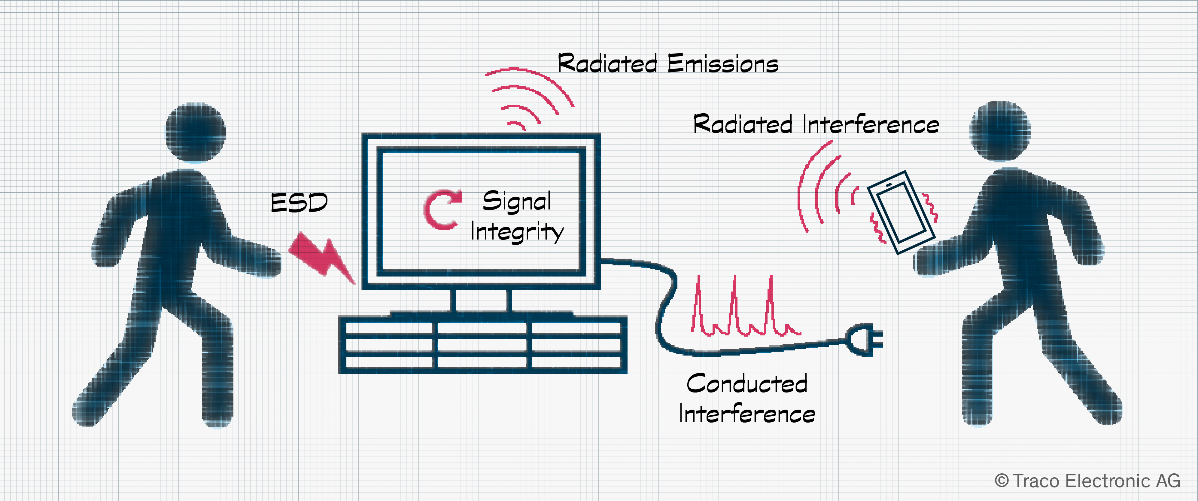
Electromagnetic compatibility, or EMC, encompasses four key aspects that must be checked before a device can be sold. It covers:
-
Emissions – limits on the power of emitted signals by the product that could interfere with the operation of other devices in the vicinity. Emissions may be radiated, such as from a smartphone or Wi-Fi router, or conducted along the cable from a power outlet or power supply.
-
Immunity – the ability to operate correctly despite interference from other devices in close proximity.
-
Signal Integrity – avoiding generating signals that interfere with the appliance’s own operation.
-
Electrostatic Discharge (ESD) – protection against high voltage discharges when a human touches the device.
If a device, such as a television or radio, shows signs of incorrect operation, such as unwanted sounds being generated or a disrupted image, it is said to be suffering from electromagnetic interference (EMI). EMI may be conducted, through power or communication cables, or radiated.
What standards are there for EMC?
Fulfilling EMC requirements requires more care and effort in the product’s design. This can range from simple, low-cost measures, such as the addition of a ferrite bead, to the more complex, such as the design and installation of custom shielding. To ensure measures to fulfill EMC don’t spiral out of control, organizations such as IEC (International Electrotechnical Commission) and CISPR (Comité International Spécial des Perturbations Radioélectriques) set different requirements depending on the type of product and its intended use. The basic classification of standards is as follows:
-
Basic standards: These cover general rules that apply to all applications and products. The best known are the series IEC 61000-4-x.
-
Generic standards: Here, the focus is on the EMC requirements of specific environments, such as households and industrial, also known under the umbrella term ‘commercial.’ So that a product can be used, it must fulfill the minimum levels specified in IEC 61000-1/2/3/4.
-
Product and product family standards: Some environments, such as railways, must operate under especially harsh conditions. Here, standards exist to define precise requirements with test levels and performance compatibility for aerospace, automotive, medical, and military. For railways, EN 50121-3-2 is an example defining electromagnetic compatibility for rolling stock.
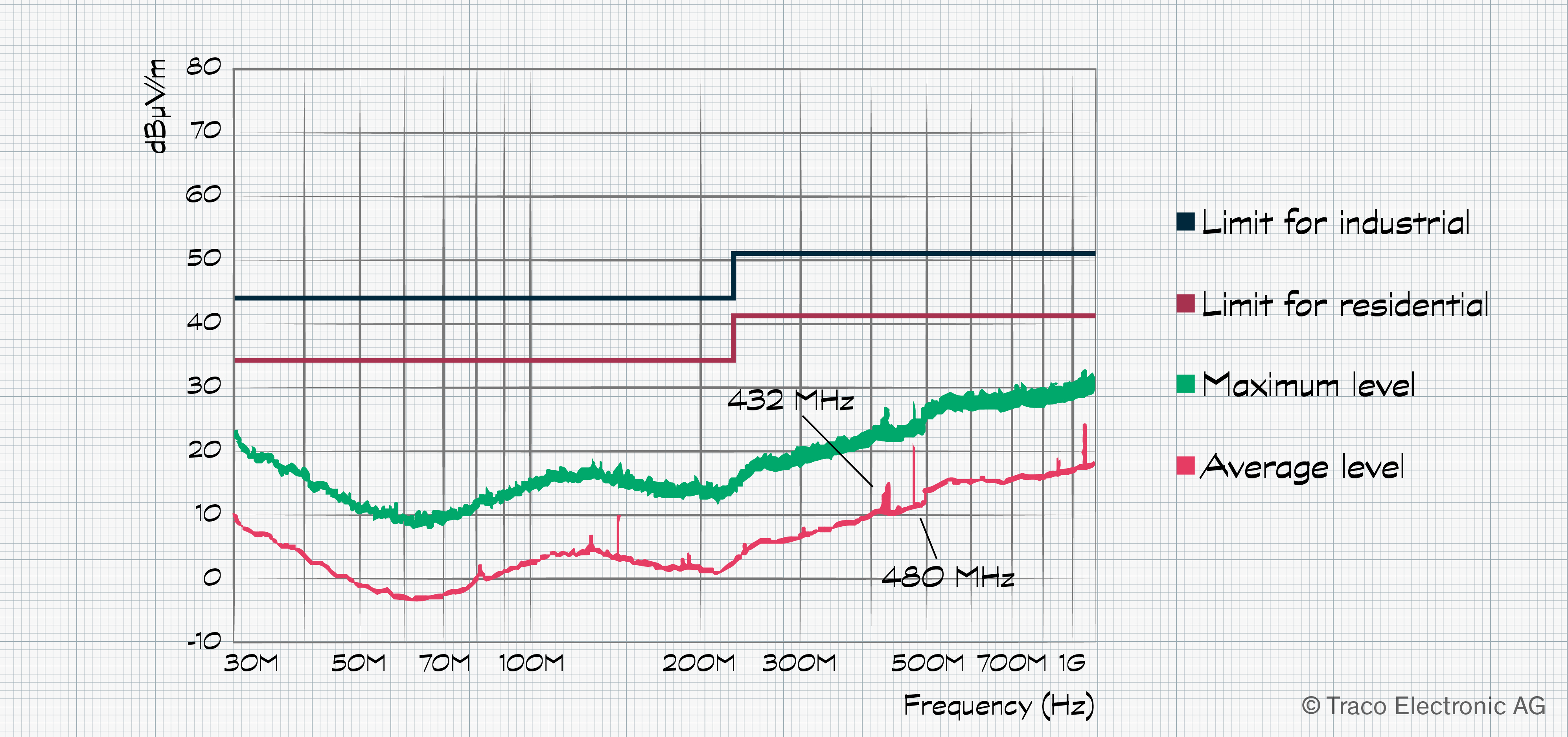
Example of a radiated emissions test results with limits
How do I avoid EMC issues?
Like many design challenges, getting EMC under control requires careful design choices right from the start of a new project. When talking to test houses, they report that as many as 50% of products they test fail the first time. Therefore, it is essential to keep the topic of EMC alive throughout your product’s development.
When sourcing modules, such as LCDs or power converters, care should be taken to review any supplied EMC test results. Additionally, it is worth checking the age of such tests. Over the lifetime of a product, individual components may have been changed due to an end-of-life announcement, and this may have changed the module’s performance. It is worth considering having an independent test house re-test modules for critical designs.
EMI issues are usually traced to printed circuit board (PCB) layout and connecting cables. All these issues are most easily tackled through good design practice rather than trying to fix them after issues appear. Some of the recommendations include:
-
Eliminate disturbances as close as possible to its source
-
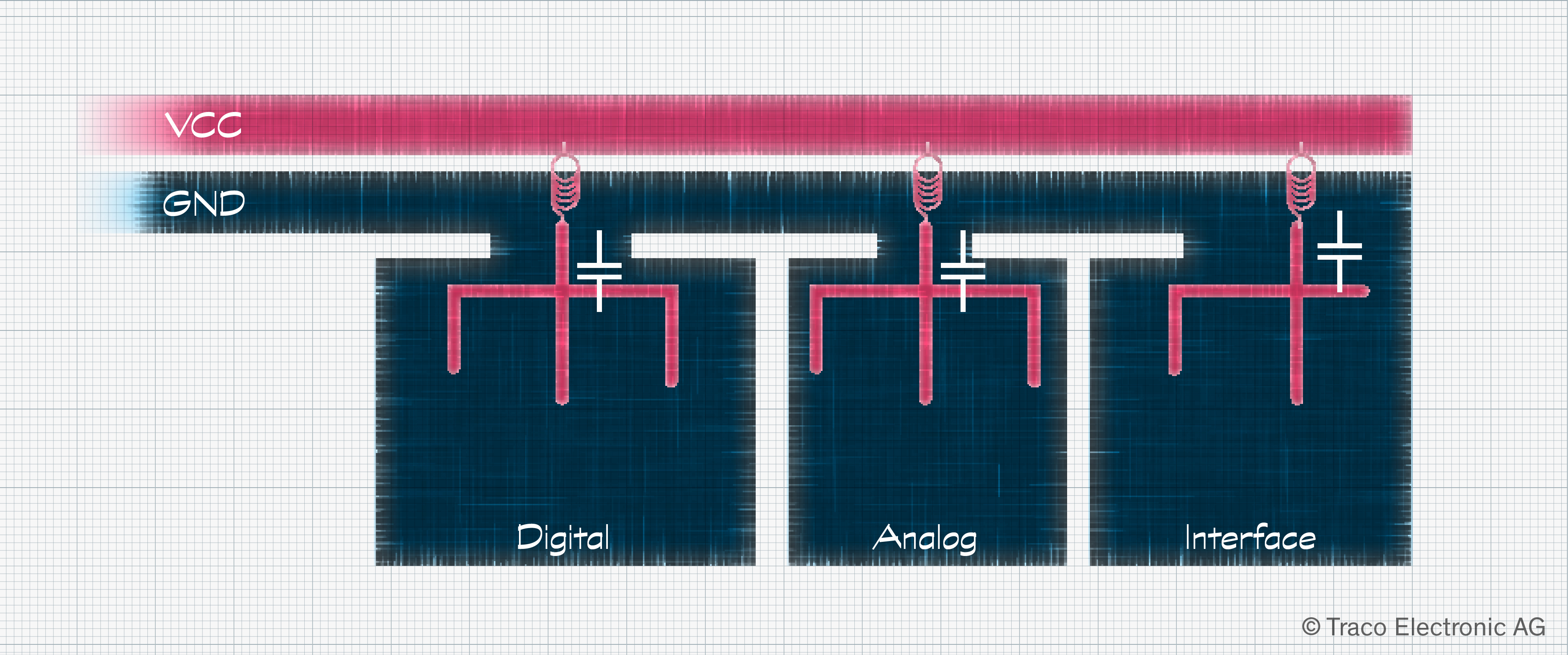
Partition the PCB according to current switching and frequency characteristics of the design.
-
Try to keep signal lines as short as possible.
-
Place filter capacitors as close as possible to the components they are protecting.
-
Widen power and ground traces to reduce their impedance.
-
Where space permits, leave different unplaced footprints for components that may help tackle EMI issues. Ferrites, capacitors, and resistors can then easily be placed later if needed.
-
Follow vendor guidance on how to connect unused pins on digital and analog integrated circuits (IC).
It should also be noted that firmware can play a role in resolving EMI issues. Microcontrollers often provide slew-rate control for high-speed switching circuits, while power ICs, such as switching converters, may offer spread spectrum switching to minimize frequency peaks.
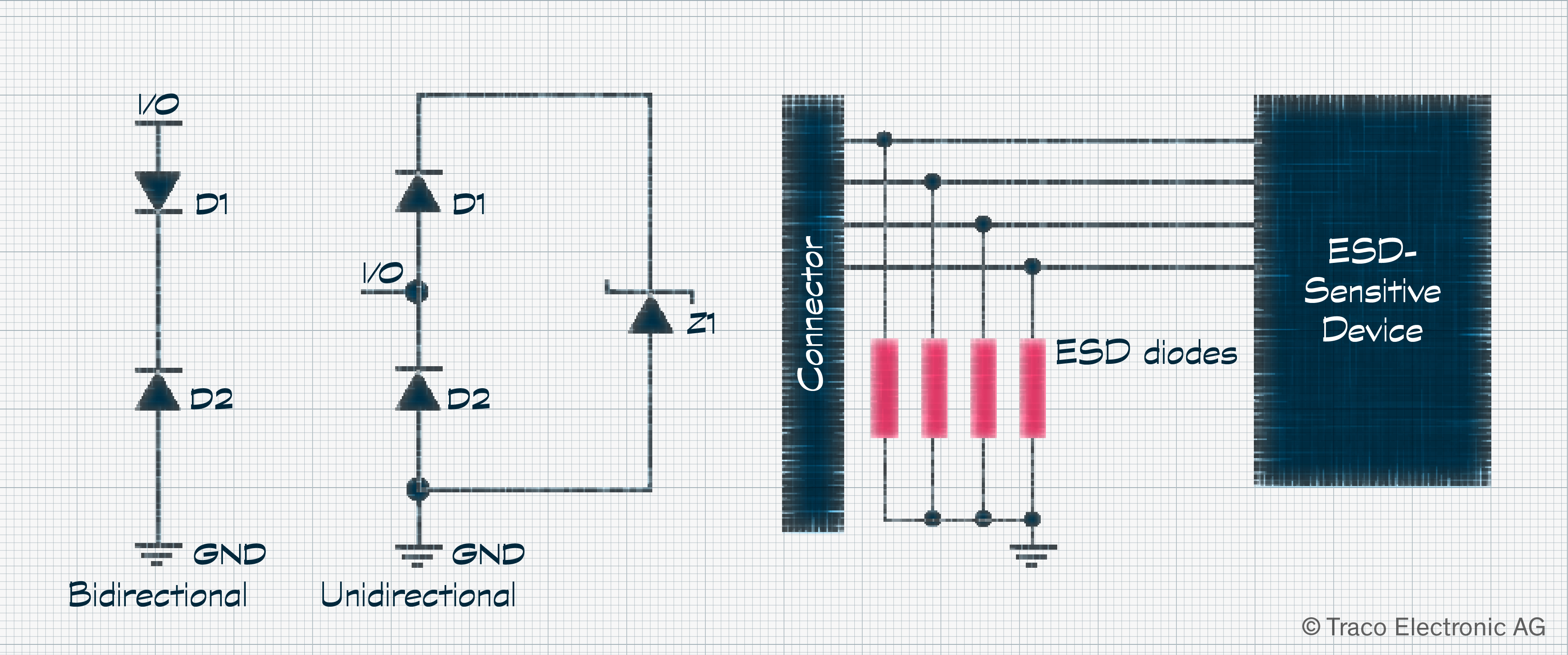
ESD testing involves injecting pulses of up to 8 kV to parts of the product that the user has access to under normal operation. There are two types of tests: contact discharge, typically to the chassis and other exposed metallic surfaces, and air discharge. Transient voltage suppressor (TVS) diodes should be added to protect each signal line entering or leaving. These must be correctly grounded with short traces. Both TVS types, bidirectional and unidirectional, short to ground during an ESD. The key difference is that unidirectional TVS diodes have a lower parasitic capacitance, making them more suited to high-speed data lines.
To learn more about the basics of EMC, read part two of this blog post here: https://www.tracopower.com/int/node/246