How to tackle electromagnetic compatibility (EMC) – Part 2
Electromagnetic compatibility (EMC) is a complex field with different standards that must be fulfilled depending on your product’s market segment. As Part 1 mentioned, EMC must be considered from day one of the project and remain under regular discussion throughout the development cycle. But what can you do to prepare without a fully kitted-out EMC laboratory?
Exploring magnetic fields in circuits with low-cost probes
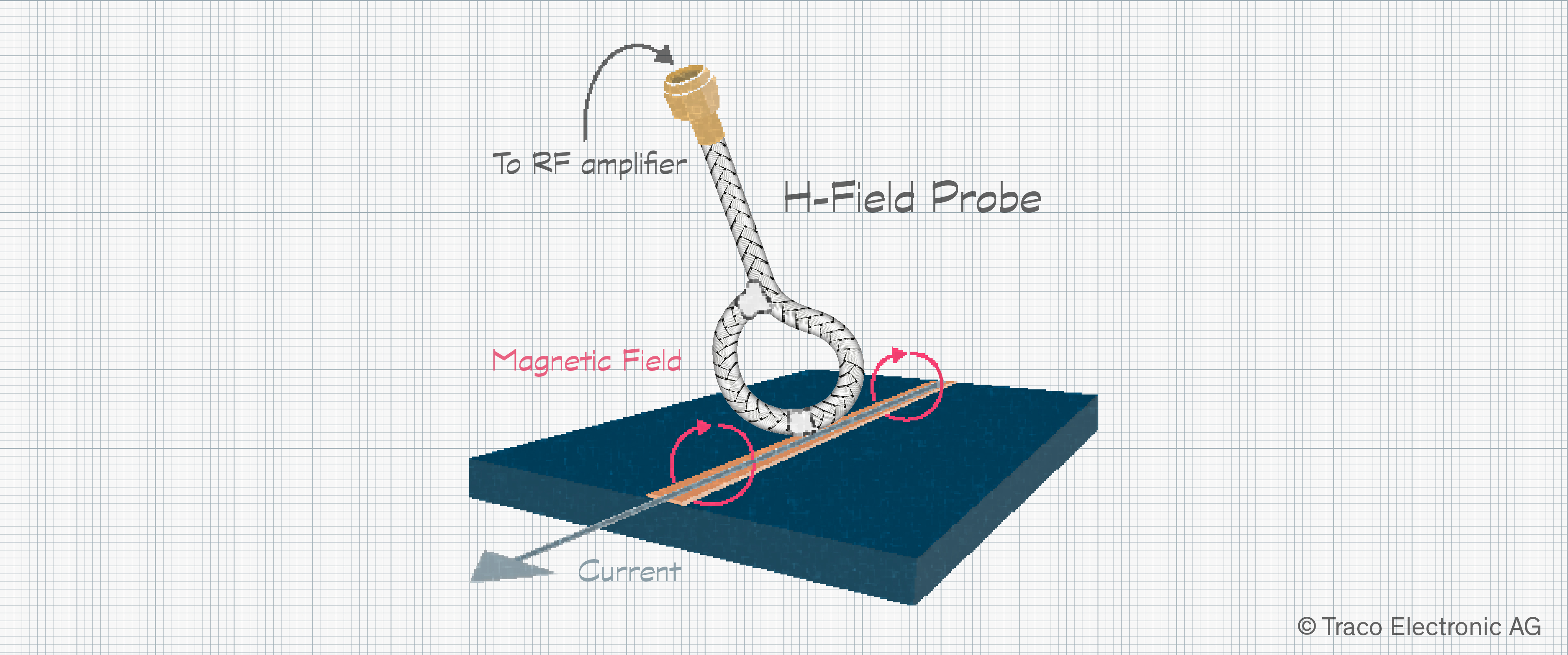
Magnetic fields, or H-fields, can be explored using an EMC probe made of semi-rigid coaxial cable coupled with an off-the-shield, low-cost RF amplifier. Forming the semi-rigid coax into a 2 – 3 cm (around 1 inch) loop, the core and shield are soldered onto itself. Then, a small shield section is removed at the center of the loop. Connected to an RF amplifier, the probe can be used in conjunction with a spectrum analyzer set to sweep from around 30 MHz. The upper limit for testing is usually 1 GHz, but you will have to work within the limits of your equipment.
If there is no spectrum analyzer to hand, an oscilloscope with an FFT function for frequency analysis can also be used. This type of testing is not about quantitative results – it is more about exploring the peaks in emissions and where they are on the spectrum. Typically, peaks can be traced back to harmonics of signals on the board, such as data communications (e.g., SPI, I2C), crystal oscillators for microcontrollers, and switching signals from power devices.
Examining electric fields in circuits with low-cost probes
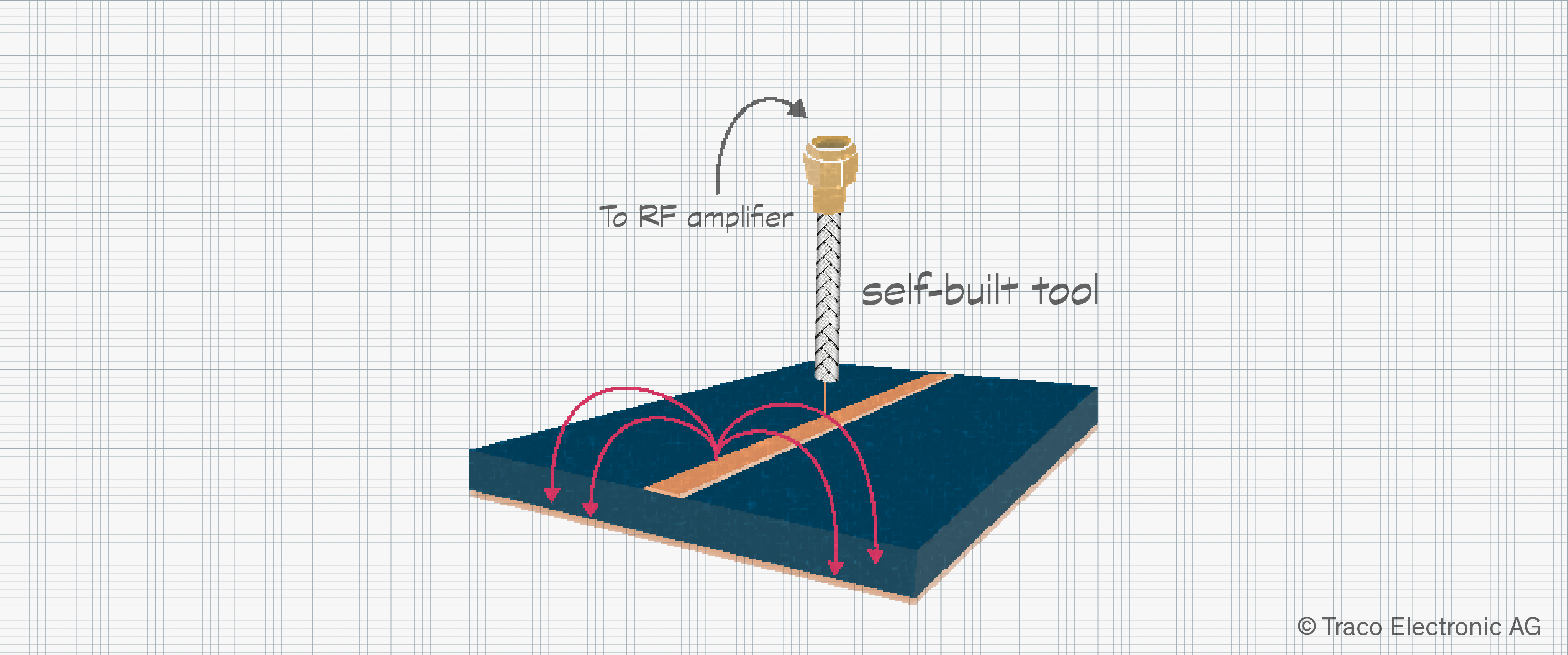
A similar approach can be taken to examine electrical, or E-fields, in your circuit. Again, a piece of semi-rigid coax can be used. Many such cables already have a connector fitted, so this makes construction and use even more straightforward. A short section of shield and dielectric are then removed, leaving a short exposed length of the central conductor.
The probe is essentially a monopole antenna and can be used to undertake near-field analysis of the circuit. Holding it perpendicular to traces or cables, it is possible to explore possible issues and troubleshoot. Again, like the H-field probe, this method delivers qualitative data, so be sure to hold the probe in the same place each time to attain results that can be compared to learn the impact of changes.
ESD and conducted immunity
The equipment required for radiated emissions can get quite expensive, but that needed for undertaking pre-compliance of the remaining EMC tests is much cheaper. For conducted emissions, a used Line Impedance Stabilization Network (LISN) can be acquired inexpensively. Combined with a spectrum analyzer or oscilloscope’s FFT, any potential issues can be found quickly, delivering peace of mind before submitting your product for testing.
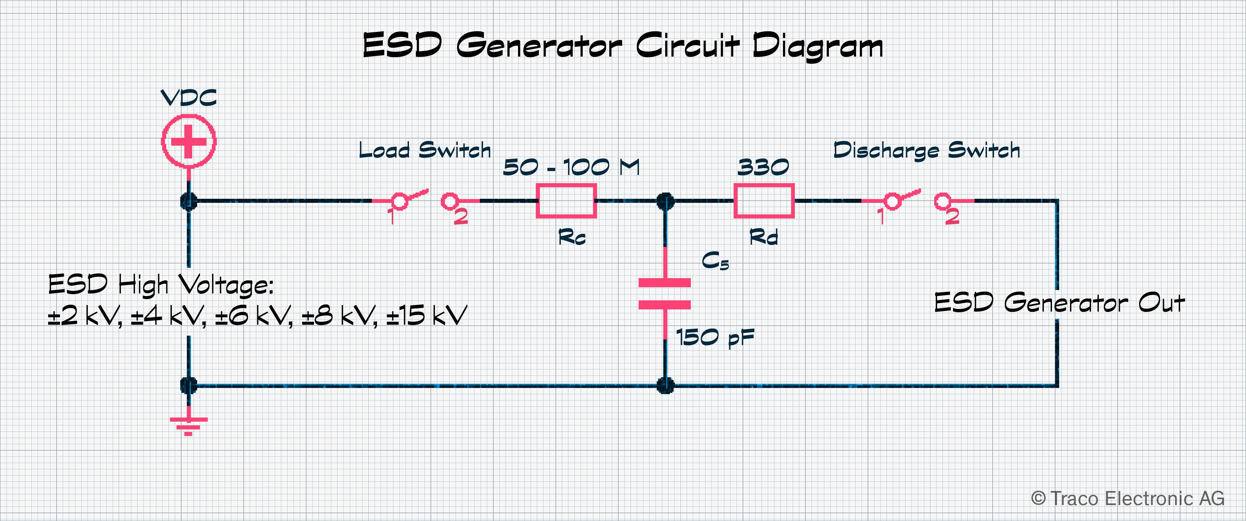
An ESD generator is also simple to construct, as the circuit is provided in IEC 61000-4-2:2008, but it requires a variable high voltage supply, something most people don’t have lying around. Another critical aspect of the ESD tool is the shape and size of the discharge tip. Luckily, the same standard also provides guidance on this. If issues are found, the application of ESD pulses can be traced using the H-field probe described above. Once the dominant path of the ESD current is determined, changes can be made to mitigate the issue.
EMC compliance testing at a test lab
As already highlighted in Part 1, around half of all products fail their first EMC compliance testing at a test lab. If you and your team are new to EMC testing, or you are working with a new technology, such as a switching power converter, for the first time, it is worthwhile contacting the EMC testing center you plan to use as early as possible. Their experts will be able to provide advice and may offer to support you during design reviews. This will save valuable time during testing and massively reduce the outlay needed for PCB reworking.
When it comes to testing day, there is plenty to prepare. While the functionality of your application may be well defined and clear, the lab will want to place the unit under test in a mode that exercises it to the fullest extent. This may require a dedicated version of firmware for test purposes. Ensure all interfaces, actuators, and wireless functionality can be placed simultaneously in an operational state to offer a worst-case operational scenario. Also, ensure that unit operation and the process for firmware updates are clearly documented. Ideally, keep the setup for testing purposes as simple as possible.
It must not be forgotten that your device needs to be tested with all the auxiliary elements required for full operation. This includes power supplies, external drives or memory cards, cables, and plug-in cards. Your team should, however, be sure that these peripheral devices are fully EMC compliant in their own right. To be on the safe side, provide two or three alternative devices, especially power supplies, as these can be damaged during surge testing if tested. Actuators and similar can be replaced with dummy loads if needed.
Much of EMC compliance requires good design practice and an appreciation for the laws of physics. Most issues only need a simple rectification, but the closer your team is to project completion, this gets more expensive. With the availability of second-hand equipment, it is possible to construct a pre-compliance lab relatively cheaply, but you will need to balance this against the amount of use it will get. For sure, getting help, either from a lab or a consulting engineer, is an excellent idea. The lessons learned can be applied to future projects as EMC competence grows in-house.
To read the first part of this two-part blog, click here: www.tracopower.com/ch/node/245