Selecting Power Supplies – Part 1
How do I specify my power supply requirements?
When designing a circuit or system, the point in the project will arrive where the power supply has to be selected. The best approach at this point is to list the requirements most important to your application. This will always cover the input and output sides (voltage and current) and other key non-electrical requirements, such as environmental parameters.
However, when you access the datasheet of a seemingly suitable power supply for the first time, its contents can be somewhat daunting. Obviously, plenty of data is provided. But, compared to the requirements you’d prepared, there is likely much more information than you might expect. The question is, how important is this data, and must it all be considered in all cases?
Datasheets have evolved over the years, and each power supply vendor has their own style and layout. This can make it challenging to compare units from differing vendors, but it should make it easier to compare different models from the same vendor. While not all the information is equally important, it is all there for a reason. Someone, at some time, has requested the information often enough for the vendor to decide to include it for all their customers. The trick is determining which datasheet entries are essential for you and your application.
Here we work our way through the basic layout of a datasheet to understand what each entry specifying the input side means.
One product datasheet, many models
A single power supply product may cover many different input voltages, output voltages, efficiencies, and output current options. Rather than create a datasheet for every option, the datasheet will cover many different models with the same basic housing and mounting, features, and targeting the same application space (e.g., railway, medical, industrial). The first page provides a basic overview of the family’s capabilities and a short description applicable to all devices.
A table of specific devices follows this. Here, core differentiating model features, such as the input voltage, output voltage, output current, and efficiency, are provided along with the order number for each model. However, what exactly appears at the beginning is model specific, so if a parameter is missing here, it probably has more variation between models and is listed later in the datasheet.
There may be further model-specific specifications, but these will be found later where the relevant specifications are given. This helps to aid the readability of this first section. Specifications that vary with model but won’t be listed in such tables are aspects such as ripple and noise, and capacitive load.
Understanding power supply input specifications
This section defines the limits around the input side of the power supply. Not all of the specifications covered here will always be included – it will depend on the particular features and capabilities of the power supply and whether or not they were covered in the table of models.
Input voltage range
The upper and lower limit for voltage is provided for alternating (AC) and/or direct current (DC) inputs. Some power supplies can operate from AC and DC; if so, this will be made clear here. For AC models, input supply frequency limits are given.
Input current
The maximum value provided allows you to ensure that power supply cables or circuit board traces are suitably dimensioned. Provision of the no-load current at nominal input voltage allows checking of the power supply if there is concern it may be faulty and allows estimation of the standby current draw.
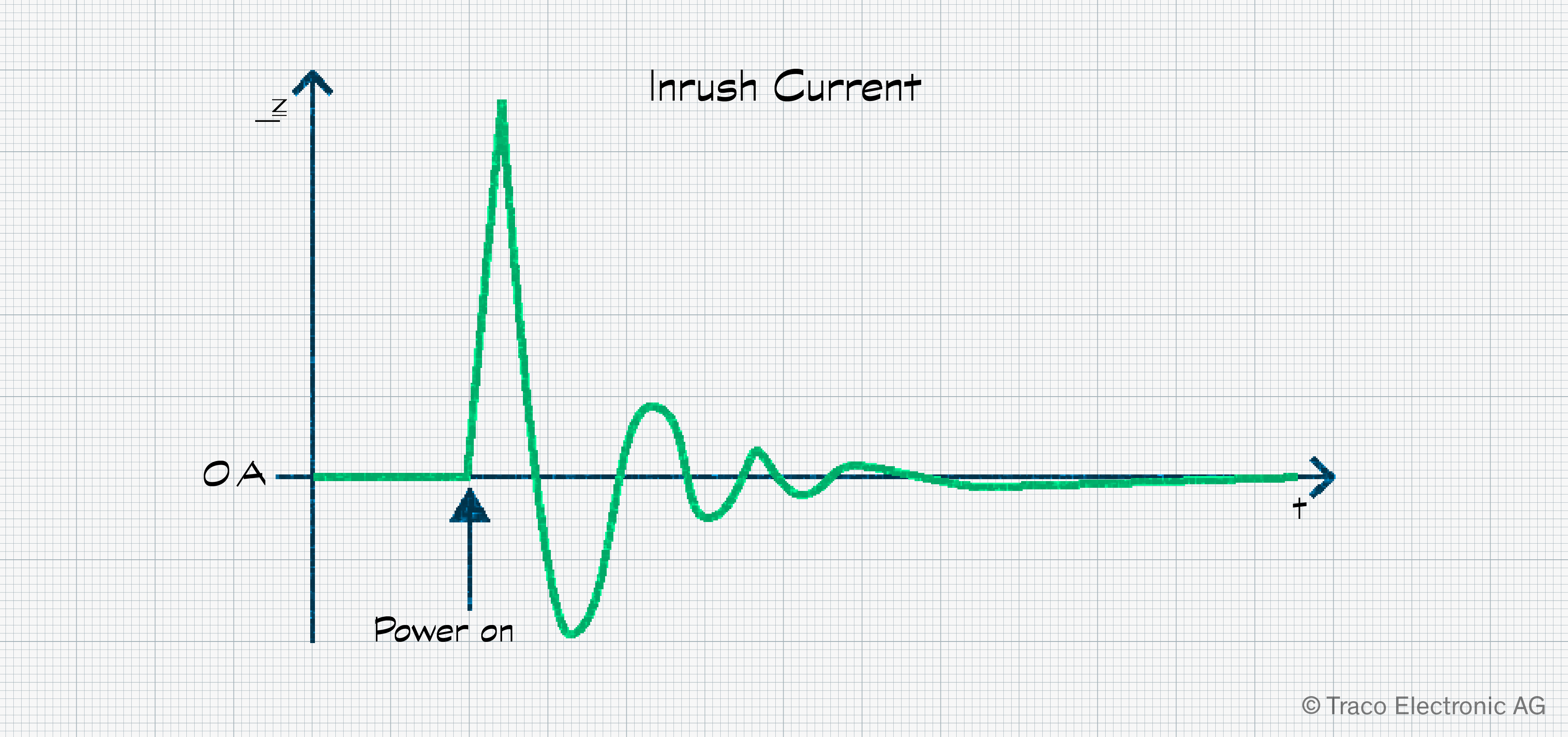
Inrush current
As the power supply is switched on, there is an initial rush of current into the unit as capacitors and transformers are energized. The value of this current peak varies with many factors, including input voltage, its slew rate, and ambient temperature. While such peaks may be many times the stated power supply current rating, the peaks return to nominal levels within a few milliseconds. Additionally, there is no risk to a slow blow fuse or type C circuit breaker. It should be noted that the inrush current is not related to the load attached to the power supply as, at this point, the load is not being supplied.
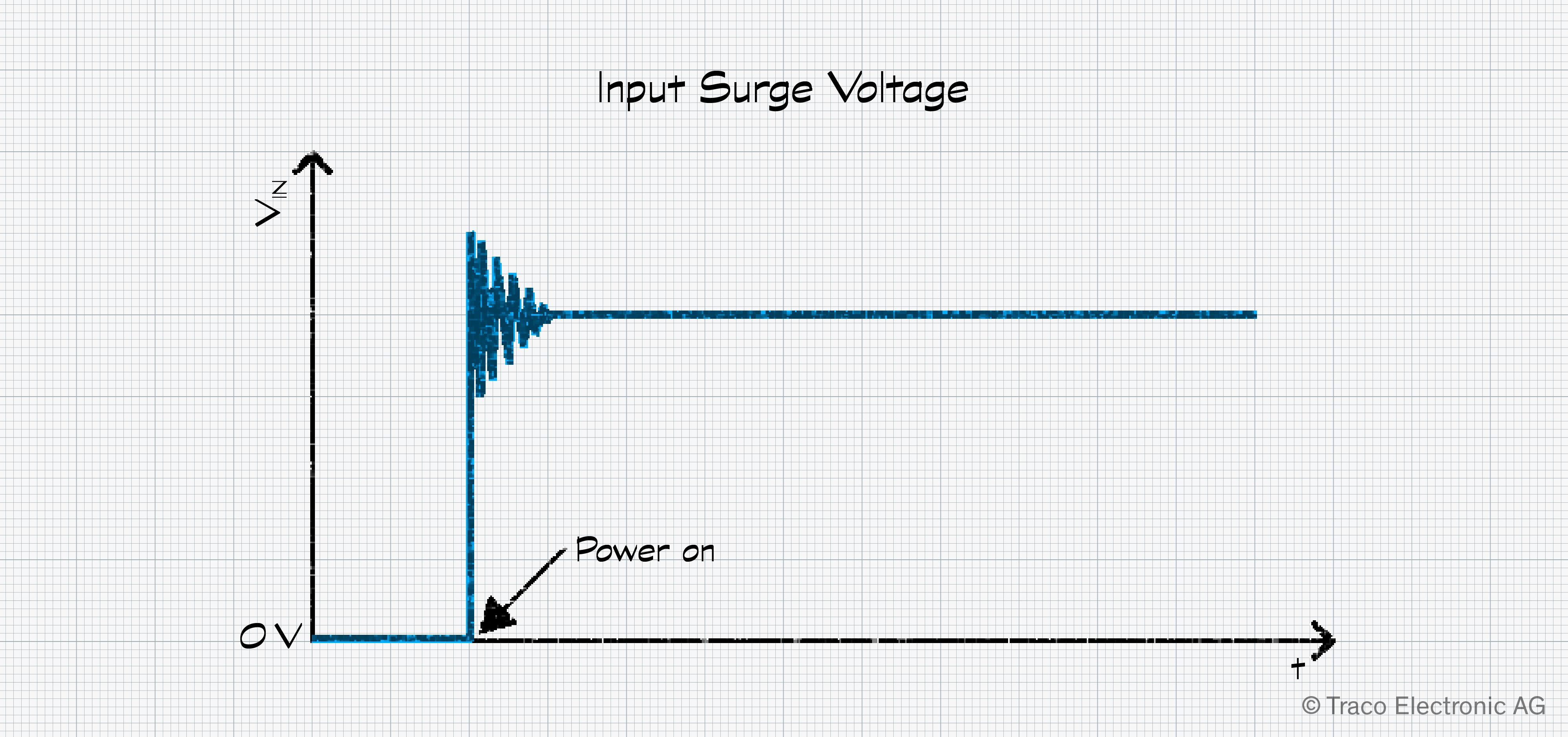
Input surge voltage
Upon start-up, the input voltage to a DC/DC converter can be observed to overshoot. The level of overshoot depends on the circuitry around the converter and may put the converter at risk of damage. Surge voltage defines the maximum voltage and duration the converter can withstand, allowing the team to assess the potential risk and develop a mitigation strategy. This specification should not be confused with the surge specification in the EMC section of the datasheet.
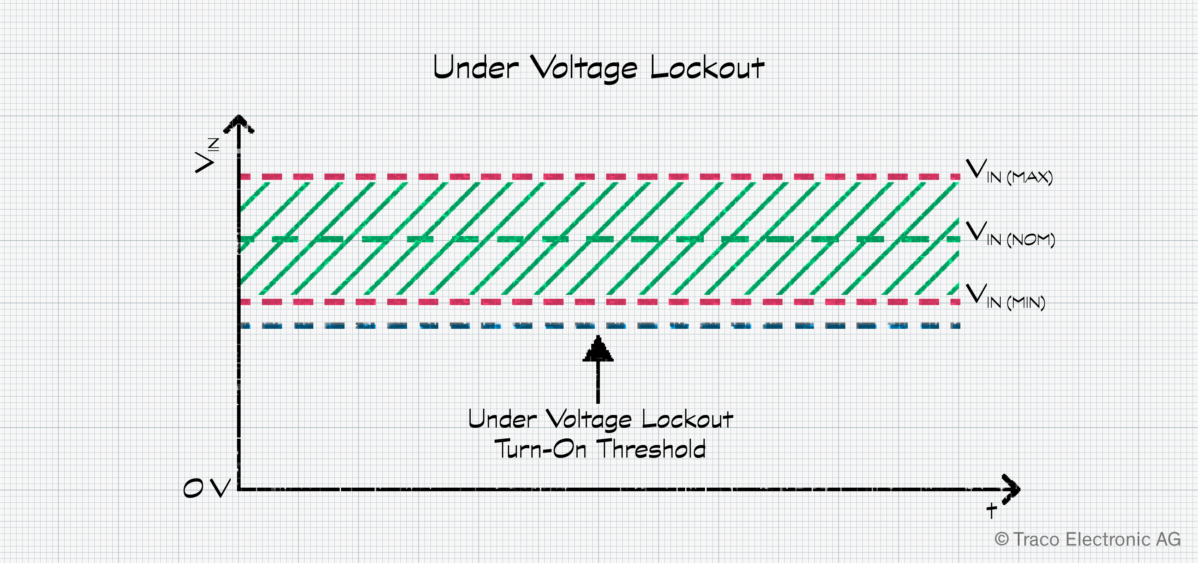
Undervoltage lockout
While a power converter is guaranteed to operate down to VIN(min), clarity is sometimes required regarding the operation below this level. If an undervoltage lockout value is given, this is the point below which the converter will definitely switch off. This can help when designers want to understand what will happen when small dips in the input voltage occur. All power supplies will cease to function at some point below VIN(min) but without a lockout specification, there is no clarity as to when this will happen or if it is the same point across all units installed.
Input protection, fuses, and filters
If included, a description of the input protection informs the design team of the power supply’s internal fuse type and rating. This is purely informative. An input fuse may also be recommended. This is to protect the circuit supplying the converter, not to protect the converter itself. Such information allows the sourcing of a suitable fuse or type C circuit breaker. The filter style may also be given, which may be helpful if additional input filtering is under consideration.
Reflected ripple current
Sometimes referred to as “back ripple current,” this parameter indicates the pulsating current draw caused by switching spikes related to the converter’s switching frequency. It manifests itself as high-frequency current disturbances superimposed on the DC input current. The wiring or tracks to the converter, acting as an antenna, typically radiate this noise.
Reverse voltage protection
This feature is rarely available as it is implemented using a diode parallel to the input. Should the polarity of the input wiring be switched, the converter is protected, but it results in a short circuit for the source, which could cause damage unless a fuse or circuit breaker is in place.
Further details on power converter specifications
In this first blog post on understanding power converter specifications, we’ve looked at the first page of datasheet information and how the input specifications are defined. Of course, there is much more to consider. In our next blog post, we’ll thoroughly review the output specifications, clarifying all the options open for consideration. Then, in the final blog on this topic, we’ll examine the general specifications that cover everything from environmental information to thermals and soldering profiles.
To read our next blog covering the input specifications of power converters, please click Part 2 and Part 3.