EMC Phenomena – Part 2
Testing for and Protecting Against Electromagnetic Phenomena – Part 2
Electromagnetic phenomena are a bit of a black art for many engineers, especially for those just starting their careers. An otherwise perfectly functional system suddenly operates erratically at one specific customer, or a batch fails in the field after thousands have been installed. Once all the traditional failure causes have been discounted, it’s time to delve into the murky world of electromagnetic susceptibility (EMS) and interference (EMI). The funny thing is, once an EMS or EMI cause has been found, it seems obvious why the issue occurred.
In the first blog on this topic we covered two EMS challenges: electrostatic discharge and electromagnetic radiated fields. Here we delve further into EMS standards and testing, covering how these phenomena manifest themselves and how their effects can be minimized.
Electromagnetic Susceptibility (EMS)
Electrical Fast Transient – Burst
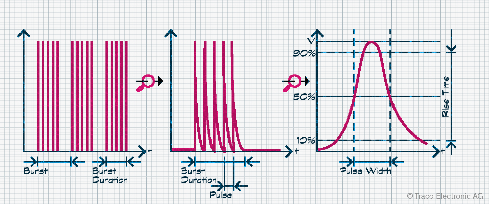
In electronics, we rarely get the chance to switch significant loads on and off. That’s why getting into an electrical distribution cabinet, with its big chunky switches, causes a little bit of excitement! And, as you hear the satisfying ‘clunk’ of the switch, you can sense the surge of energy rushing to the load. When the load is inductive, such as a motor, contactor, or relay, a signal burst with voltages of up to a few kilovolts and rise times of 5 to 15 nanoseconds can be injected into the AC line. This is known as an Electrical Fast Transient (EFT) or simply as a “burst”. The very short rise times cause broadband interference up to high frequencies.
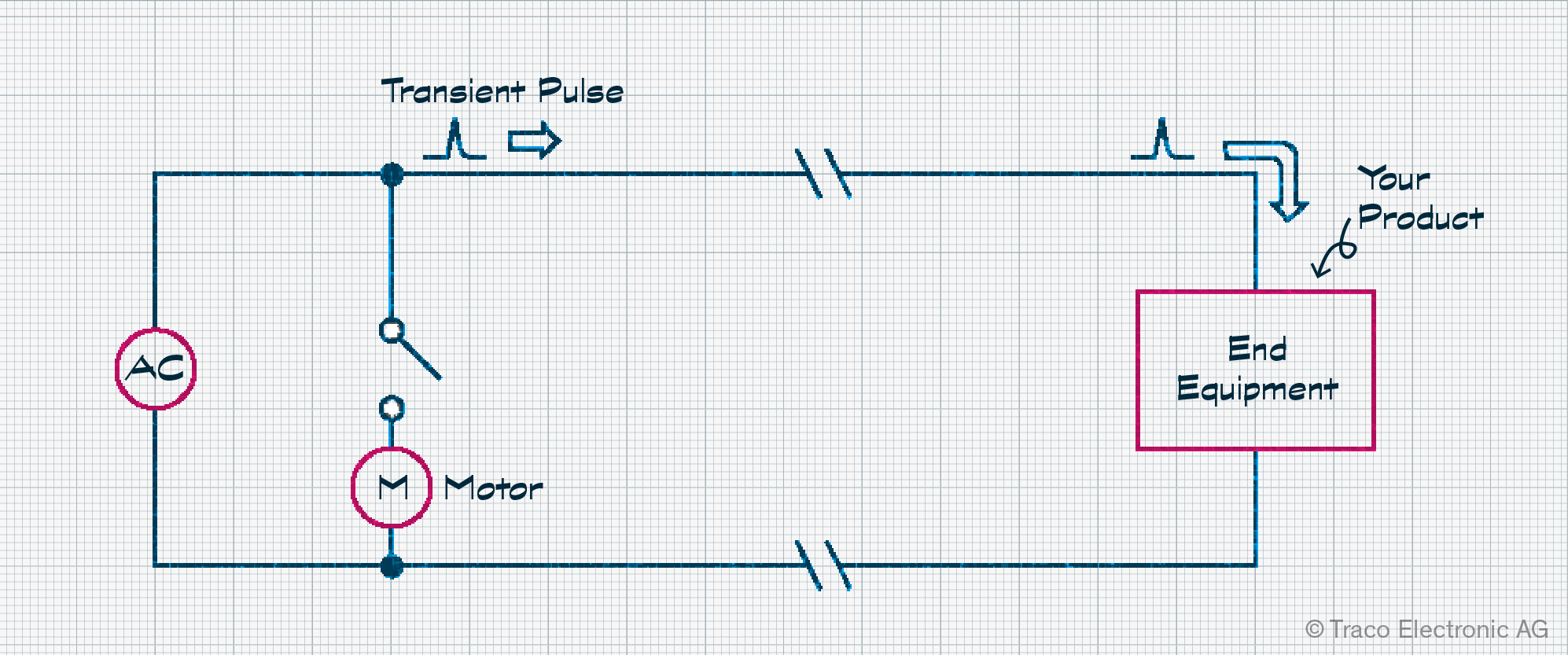
If your application is unfortunate enough to share the same wiring, a range of EFT side effects can occur. Thanks to coupling effects, the resultant noise can pass through AC and DC power stages and signal lines into your electronic system. This may cause an unexpected system reset, possibly triggered by a brown-out condition, disrupt data communication or analog signals, or corrupt memory contents. The application may end up in latch-up, requiring the user to reset or restart it. Worst case, physical damage requiring repair may occur.
EFTs are covered in the IEC 61000-4-4 standard that provides testing methods and test levels. Once this is determined as the cause of failure, a range of options are open to minimize or resolve the impact. Many traditional best practice recommendations include reviewing cable routing, keeping wiring short, and twisting supply or signal/ground cables. Printed circuit board (PCB) layout and placement of decoupling capacitors is another consideration, as is the use of filters, either at the power inlet, connectors, or on the PCB. Like many other EMS challenges, such physical changes result in costly redesigns, so it is worth testing early or making provision for additional capacitors and ferrites in your design.
Surge
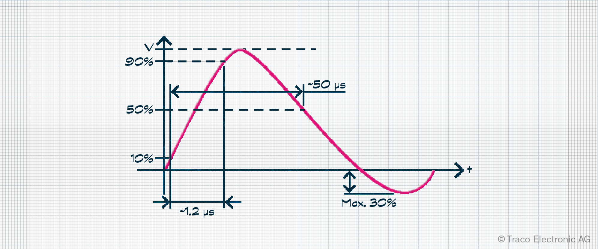
Electrical surges result from two main sources. The first is the power grid as the result of electrical switching or failure of equipment attached to it. The second is from lighting strikes. The "standardized surge” is characterized by a single pulse that can peak between 250 V and 4 kV, peak currents up to 2000 A, and lasts for 50 µs, as described in EN 61000-4-5. The test circuit for a surge generator and the approach to protecting against surges is very similar to that for ESD.
One protection approach is the transient voltage suppression diode (TVS), but others exist. Metal oxide varistors (MOV) are surge absorbers with high impedance until a high voltage is applied, at which point it becomes low-ohmic, shunting the surge current. However, they do deteriorate over time through use and may fail. An inductor-capacitor (LC) circuit may also provide the required protection; in some cases, a combination of these solutions may be the answer.
Conducted Radio Frequency Field
As already discussed in Testing for and Protecting Against Electromagnetic Phenomena – Part 1, radiated radio frequencies (RF) can disrupt the functionality of your application. But conducted RF can be just as problematic and results in similar issues, such as impacting the quality of analog measurements and increasing noise. As soon as you have any cables, from power to communication, you’ll need to look at EN 61000-4-6 for advice on testing approaches.
One method uses a coupling decoupling network (CDN), directly injecting RF into the cable, which is typically the preferred testing option as it is repeatable. CDNs are available with connectors suitable for testing both screened and unscreened cables, from AC power cords to USB and HDMI, to name but a few. The setup uses an RF signal generator with an integrated power meter, calibrated with a 150 Ω impedance before attaching the equipment under test (EUT).
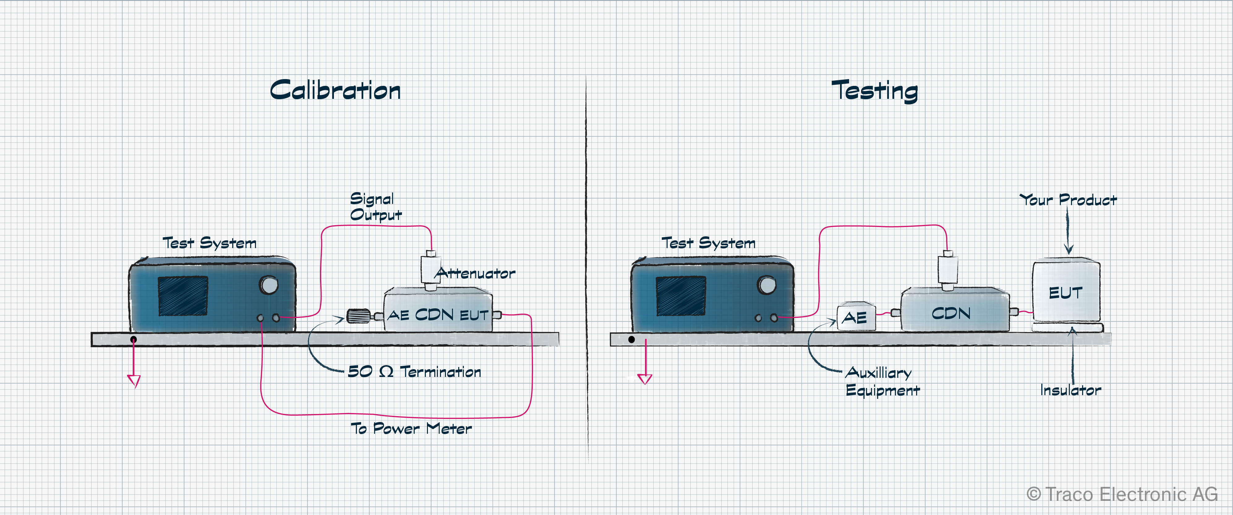
Frequencies from 150 kHz to 80 MHz are used, although this can reach 230 MHz for some applications, and the signal used is amplitude modulated (AM) at 1 kHz with a modulation depth of 80% ranging from 1 V to 10 V RMS. Alternatively, an electromagnetic (EM) clamp or bulk current injection (BCI) method may be used, but these require significantly more RF power to attain the same conducted RMS voltage in the cable. Testing involves exercising your application while the interfering signal is injected. Should your product operate correctly, the test is considered passed.
Power Frequency Magnetic Field
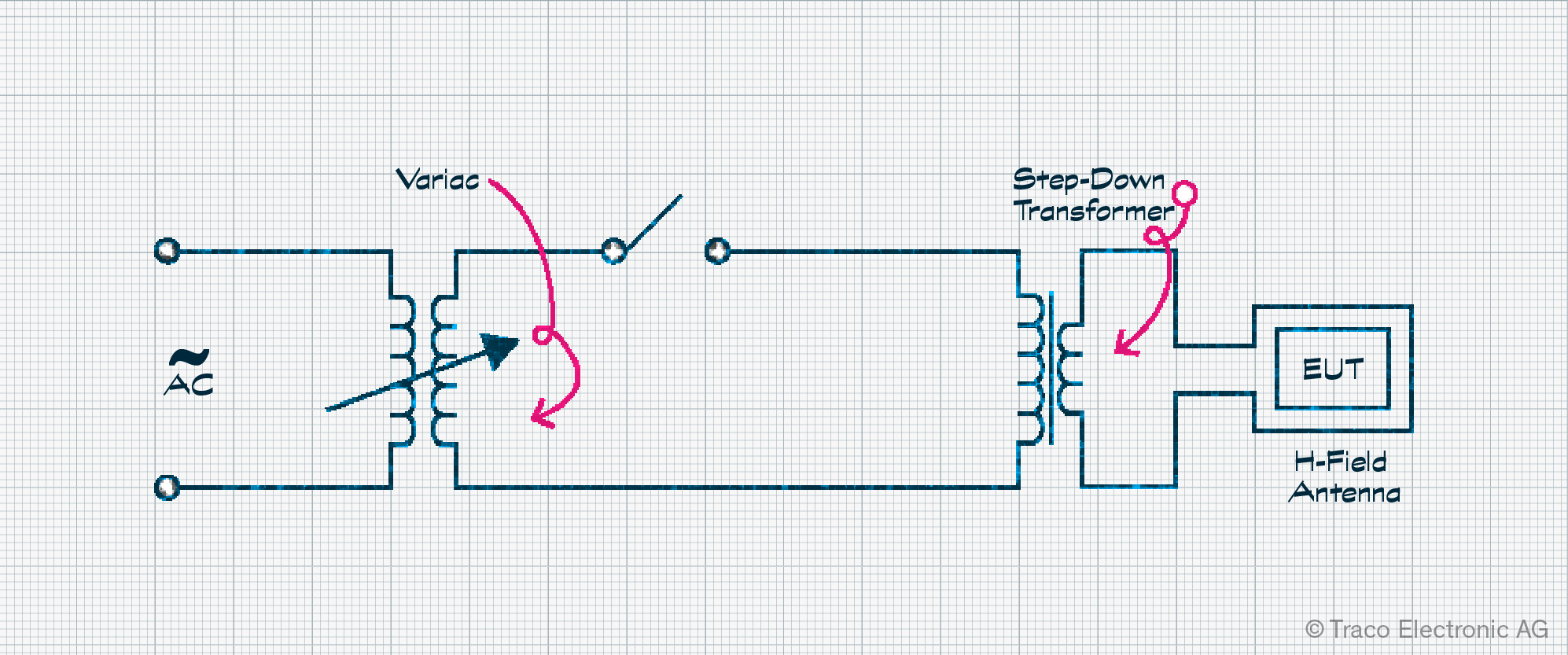
Not only do we have to deal with interference from RF signals, but we also have to review the impact of magnetic fields too. Generally speaking, testing to EN 61000-4-8 is limited to magnetically sensitive applications. This includes but is not limited to, equipment using Hall sensors or sensitive medical devices. For example, a 50 Hz field of 3.2 A/m (4 µT) would generate an electrical signal of around 1 µV in a loop area of 80 cm2. For reference, this is the lower-end field strength from a microwave oven measured at a distance of 30 cm.
Testing is typically implemented using an antenna that is large enough for the EUT to sit inside, driven from a 50/60 Hz mains line. In some cases, the frequency may also be swept and modulated. Unfortunately, resolving magnetic field issues is challenging and costly. Many issues will require changes to the PCB, although changing components to ones less susceptible to magnetic fields is also an option. Shielding is possible, but its impact is limited. For example, 3 mm thick steel reduces a 50 Hz field by 20 dB, but aluminum shielding would need to be significantly thicker to achieve the same result.
Voltage Dips and Interruptions
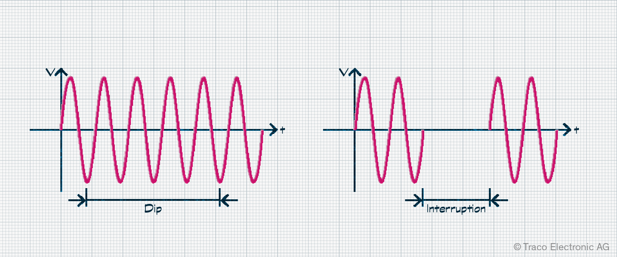
It is not only surges that can cause issues for your application. Should you be powered from a consumer outlet or three-phase, 50/60 Hz supply, you’ll also have to contend with voltage dips, interruptions, and possibly voltage variations. Dips are defined as a percentage reduction in the nominal voltage of the supply for a set number of cycles, a situation typically caused by other equipment being started. Interruptions are periods when the supply drops completely for a half-cycle or longer. EN 61000-4-11 covers the testing procedure, and a range of test systems on the market offer fully automated testing.
Designers of AC/DC converters need to deal with this to ensure that the output remains steady. If your equipment uses a compliant AC/DC power supply, you shouldn’t have any issues. However, if you are having issues with latch-up, causing the user interface to lock up, loss of settings in memory, or even unexpected system resets, this could be your cause. Should a tested device malfunction due to this test, it is considered to have failed.
Planning for EMS issues is best
While you and your team spend time defining the correct size of icons on the display and the optimal sound for tactile feedback, a host of environmental conditions risk making that all irrelevant once your device is in the field. Understanding these standards, the impact each phenomenon causes, and how testing is executed is time well invested. Product recalls quickly eat into profits and the team’s time as they attempt to replicate failures and determine probable cause. It’s definitely worth calling on EMC experts as early as possible if you have limited experience with such issues.
Don’t forget to drop by Traco’s Power Corner again soon to read the final blog on EMC phenomena, where we’ll cover electromagnetic interference (EMI) topics from conducted emissions to flicker.
If you want more information about EMC Phenomena and you have not yet read the first part, please read Part 1.
If you’re intrigued to discover the final EMC phenomena we’ve covered, take a look at our final blog on this topic, focusing on electromagnetic interference (EMI) topics from conducted emissions to flicker.