EMC Phenomena – Part 3
Testing for and Protecting Against Electromagnetic Phenomena – Part 3
Our review of electromagnetic phenomena thus far has focused on electromagnetic susceptibility (EMS). These examine phenomena external to our electrical devices that can cause them to misbehave and, in the worst case, fail. In our first blog post, we covered electrostatic discharge (ESD) and electromagnetic radiated fields. In the second blog post, we delved into electrical fast transients, conducted RF, and voltage dips and interruptions. In each case, we’ve explored the standards that define the acceptable limits of these phenomena, provided examples of how testing is implemented, and offered approaches to protect sensitive circuits.
In our final blog on this topic, we’ll review some of the main electromagnetic interference (EMI) phenomena, the unwanted RF, conducted signals, and disturbances the devices you design may generate. As before, we’ll also highlight what the relevant standards are, the test limits, and how you might be able to perform some tests in your laboratory.
Electromagnetic Interference (EMI)
Conducted Emissions
Most of us are aware of radio interference. But interference can also pass from your product through mains cables to other devices. Such interference falls under the category of conducted emissions.
Conducted emissions can be common- or differential-mode. Common-mode (CM) emissions travel down a conductor (e.g., live, neutral, or a signal) to ground or earth. Differential-mode disturbances pass down and back through a pair of conductors (e.g., live and neutral, pair of serial interface wires). This knowledge is critical to tackling any failures around conducted emissions testing.
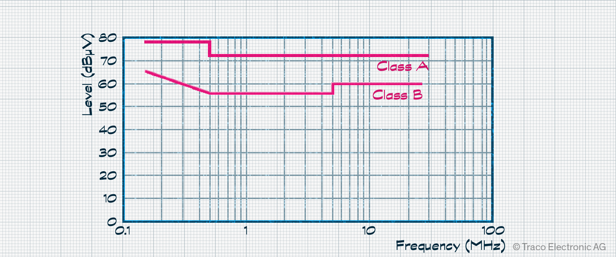
Test equipment and procedures are described in CISPR 16-2-1 to ensure a consistent approach for reproducible measurements. Testing is typically undertaken for the 150 kHz to 30 MHz range at a resolution bandwidth of 9 or 10 kHz. However, pass/fail limits are defined elsewhere. For example, EN 55032 covers multimedia equipment, with stricter Class B limits for products targeting residential environments and Class A limits for everything else.
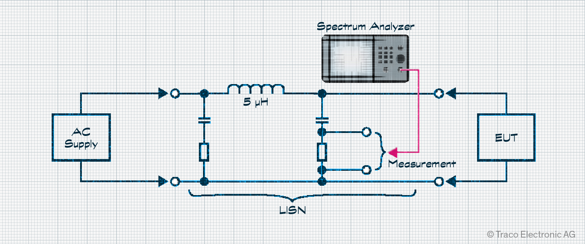
Testing requires that a spectrum analyzer monitors the equipment under test (EUT), powered by its intended power source through a Line Impedance Stabilization Network (LISN). The LISN ensures a fixed impedance of 50 Ω is in place during measurement, negating impedance variations caused by the power source used. LISNs vary in their feature set. For example, not all LISNs have built-in surge protection, so it may be necessary to disconnect the spectrum analyzer before powering your EUT on and off.
Conducted emissions tests can fail even though the off-the-shelf power supply used is compliant. Power supplies are usually tested with a fixed DC load. However, the load your EUT draws is unlikely to be flat and stable, which can cause issues. Thus, having one or even two alternative PSUs may be helpful on test day.
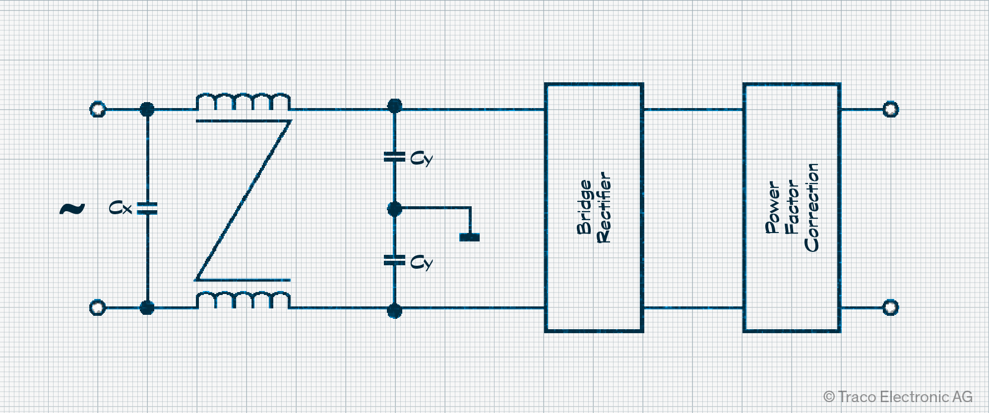
Some issues can be resolved by modifying the power supply filter. Line-to-line “X capacitors” divert differential-mode currents, while line-to-ground “Y capacitors” tackle common-mode currents. The components are paired with a common-mode choke that blocks higher-frequency signals.
However, other issues can only be resolved through physical changes. For example, crystal oscillators used with microcontrollers or FPGAs can cause disturbances at their frequency of operation due to poor grounding. This might only be fixed by modifying the printed circuit board (PCB). Problems resulting from the simpler shielding of low-quality connectors may require replacing them with higher-quality alternatives.
Radiated Disturbances
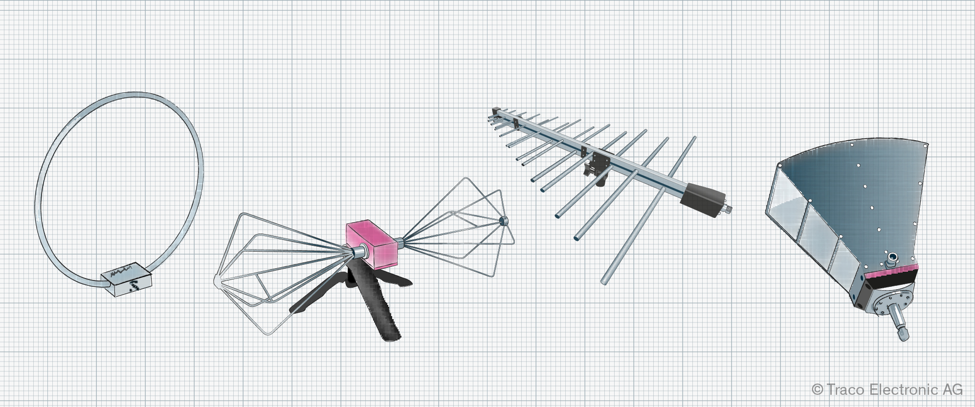
Of course, some of the disturbances are radiated as RF energy, and this is where CISPR 16-2-3 comes into play. It defines test methods and the instrumentation needed, covering the frequency range 9 kHz up to 18 GHz. Unfortunately, Wi-Fi and mobile phone masts, as well as radio, television, and telecommunication signals, make radiated emissions tests in your own laboratory challenging. As a result, you’re more likely to focus on qualitative EMC testing using an H-field probe.
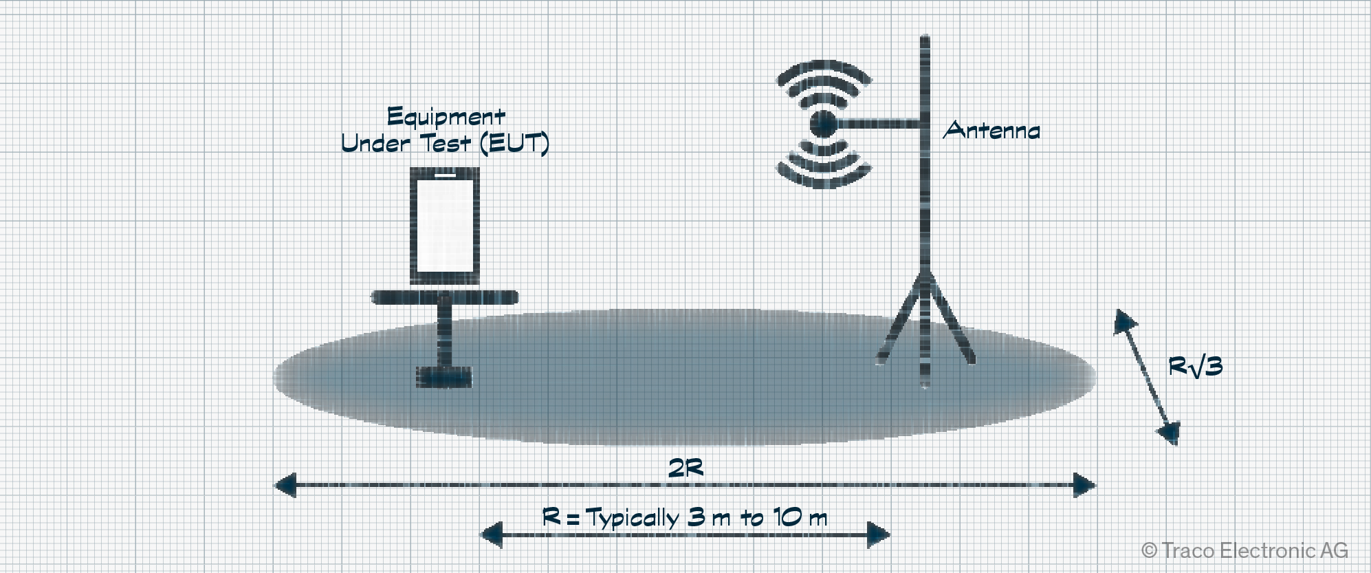
Test laboratories offer Open Area Test Site (OATS) and Semi-Anechoic Chamber (SAC). OATS is an outside testing site selected for minimal local interference. It’s prepared on a grounded area between the equipment under test (EUT), RF antenna, and test instrumentation. The distance between EUT and antenna is typically 3 m, 10 m, or 30 m. Obviously, testing is limited to days of reasonable weather, although some OATS locations have weatherproofing in the form of an RF transparent covering structure. The EUT is placed on an insulated turntable, allowing radiated emissions from every angle to be determined.
A SAC is a shielded metal room that isolates testing from ambient RF sources. Cone-shaped RF absorbers keep reflected emissions to a minimum. Unlike OATS, a SAC testing laboratory can be used at any time. However, for the operator, they are significantly more expensive to construct.
Testing is extensive, and you will be expected to switch the EUT through all operational modes. For processor-based applications, this may require a dedicated version of software/firmware to automate the process. The device must also be tested with any auxiliary equipment, such as a USB flash drive or serial interface, that may be used in regular operation. It’s worth having several such auxiliary peripherals and cables to hand during testing in case one of them is the cause of a failure.
Depending on the frequency range of testing, different antennas may be used. It may also be necessary to use an RF amplifier before connecting with a suitable spectrum analyzer. This should support a bandpass filter setting with 6 dB per decade roll-off and include quasi-peak measurements. Test limits depend on the category of the EUT. For example, CISPR 11 Group 1 testing of a Class B device covers products such as laboratory equipment, switch mode power supplies, and machine tools.
Many issues relate back to design issues with the PCB, cable layout, and grounding. In some cases, failures during testing can be resolved using ferrites, chokes, or even shielding. Failures caused by switching circuits may be resolved by enabling spread-spectrum modulation of clocks, if available.
Mains Harmonics
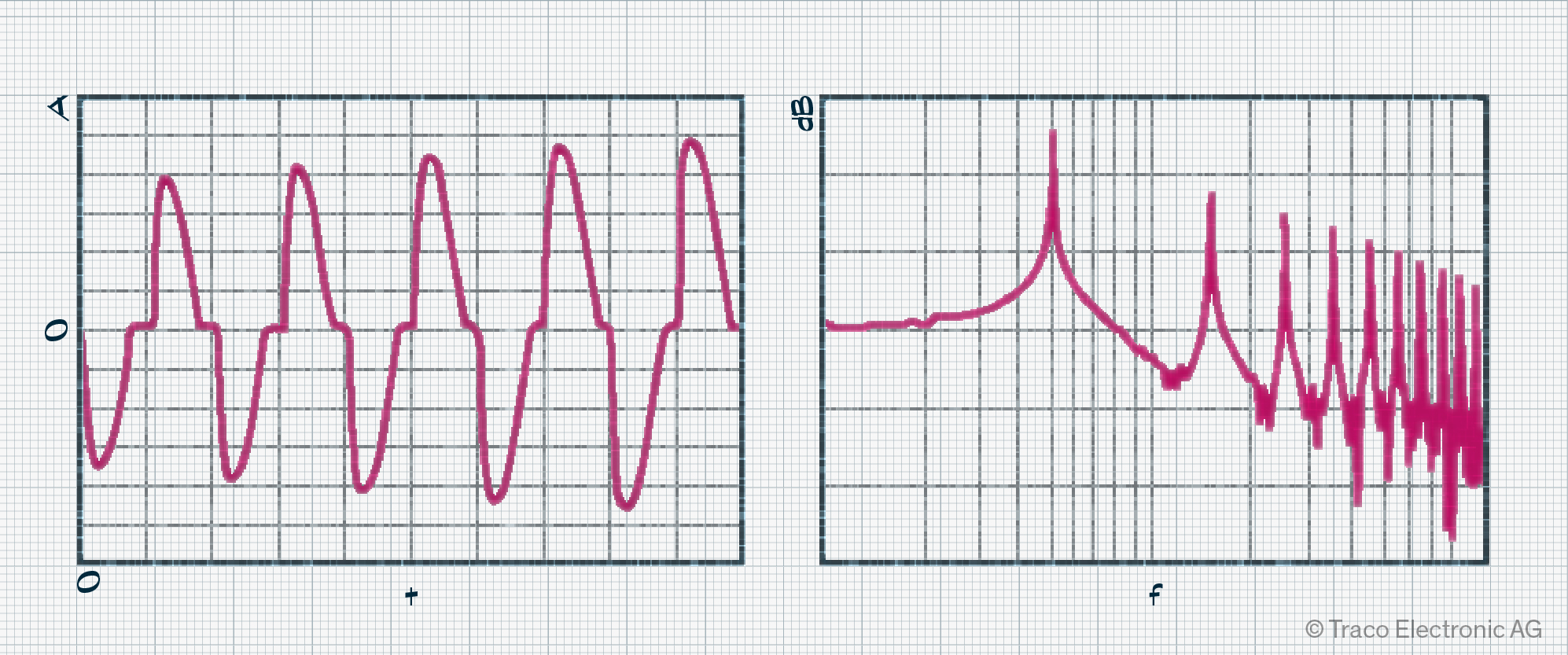
Ideally, the current draw of your equipment would be in phase with the voltage of the mains supply. However, non-linear loads have a discontinuous current draw, such as the classic rectifier-capacitor used in power supplies. The current no longer looks like a sine wave and, viewed on a spectrum analyzer, is rich in harmonic content. We must assume that our equipment generates mains harmonics and, therefore, must check if we conform with EN 61000-3-2.
This standard is restricted to equipment drawing less than 16 A and, while there are exceptions, it applies to most applications. Typically, a single piece of equipment is not an issue. Rather, it is the operation of many computers, monitors, and lamps together (such as in an office or hospital) that results in performance or unreliability issues due to the resulting combination of harmonic currents. It can also result in interference in audio devices.
Your test setup will deliver results for all or some harmonics up to the 40th order and, depending on the class your equipment falls into, a pass/fail status for each. Computers, monitors, and televisions fall into Class D, while portable tools fall into Class B. The test equipment required consists of a low-distortion AC power source, harmonic analyzer, and current transducer, a setup that usually supports flicker testing, too.
Flicker
Inevitably, you’ve experienced a moment where the lights in your home or office have flickered or dimmed for a moment. This is often caused by sag in the supply, resulting from issues with the electrical grid. But it could also be caused by local switching of a high-load electrical appliance, such as a vacuum cleaner, oven, or kettle. In the worst case, an appliance could cause continuous variation in lamp luminance, leading to headaches or even an epileptic seizure. The testing defined in EN 61000-3-3 relates to the earliest electrical installations, where degrading electrical light bulbs caused lamps on the same power line to flicker.
The standard defines limits for the voltage fluctuations that a piece of electrical equipment may generate, targeting primarily home appliances that operate at around 220 VAC and draw less than 16 A. The purpose of the standard is not to eliminate brightness variations of local luminaries entirely. Instead, it defines acceptable levels for variations in brightness.
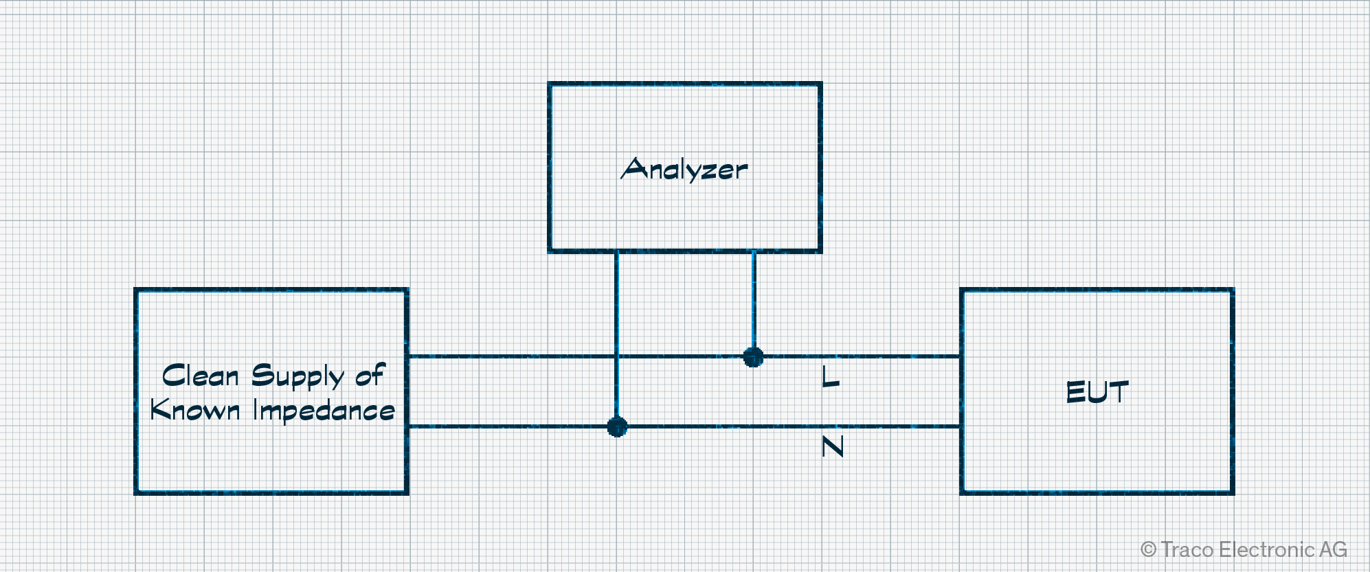
For testing, a flicker tester or analyzer is used. Combined with a clean power supply, the voltage fluctuations of the EUT’s supply terminals are monitored. Complex calculations are then undertaken to evaluate the fluctuations caused during operation. Because the flicker testing setup is similar to that used for mains harmonics testing, both types of tests are usually covered by the same instrumentation.
Conclusion/Summary
There are a wealth of standards to fulfill, all of which are designed to ensure that all the electrical equipment and appliances we use at home, in our offices, and elsewhere work as expected. As we’ve seen, testing ensures that our device doesn’t disturb those around us. But it also checks to see if our device can be disrupted by signals it may be subjected to. All of the challenges around EMC are best tackled as early as possible, and it is advisable to get support from experts or your component and system suppliers if needed. Yes, ferrites, chokes, and shields can be added later on, but they are limited in the problems they can solve and add unnecessary costs. In the worst case, you’ll have to redesign the PCB, adding weeks of delay. Finally, engage with a test house to clarify which standards apply in your case and what will be needed for test day.