Selecting Power Supplies – Part 2
How do I specify my power converter?
There are many factors to consider when specifying a power converter, probably many more than you’d casually jot down on a piece of paper. But, as we saw in part 1, some are more esoteric than others, while a few relate only to DC/DC converters. Some parameters, such as input and output voltage, are exceptionally important, and there is unlikely room for compromise. However, other items may be less critical. Therefore, when creating your ‘ideal power supply’ specification, it is also worthwhile noting the parameters that are non-negotiable and which have some wriggle room. It may also be valuable to explicitly state the parameters you have disregarded so that, should questions be raised later in the project, it is clear why those specifications were considered irrelevant.
In this next blog covering power converter specifications, we clarify what each entry specifying the output side means. The final blog on this topic will cover the remaining general specifications, covering environmental conditions, packaging, and housing.
How are power converter outputs specified?
As already highlighted, the power supply’s output voltage (nominal) and current (maximum) are typically given in the table on page one of the datasheet that provides an overview of the models in a specific series. This is insufficient to understand the output capabilities fully, so further details are provided in the remainder of the datasheet. The following covers a relatively exhaustive collection of parameters that typically arise.
Output voltage regulation
Perhaps one of the most important aspects of any power converter is how well it maintains the desired output voltage. The output voltage will vary with changes in input voltage (line regulation) and load (load regulation). This parameter indicates the change you can expect as a percentage of the nominal output voltage, VOUT(nom). Line regulation is given for the change from VIN minimum to maximum. How load regulation is defined varies but is typically given as a percentage range, such as 0% – 100% or 10% – 90%. This specification focuses on static deviation. For dynamic behavior, refer to transient response below.
Output current limitation
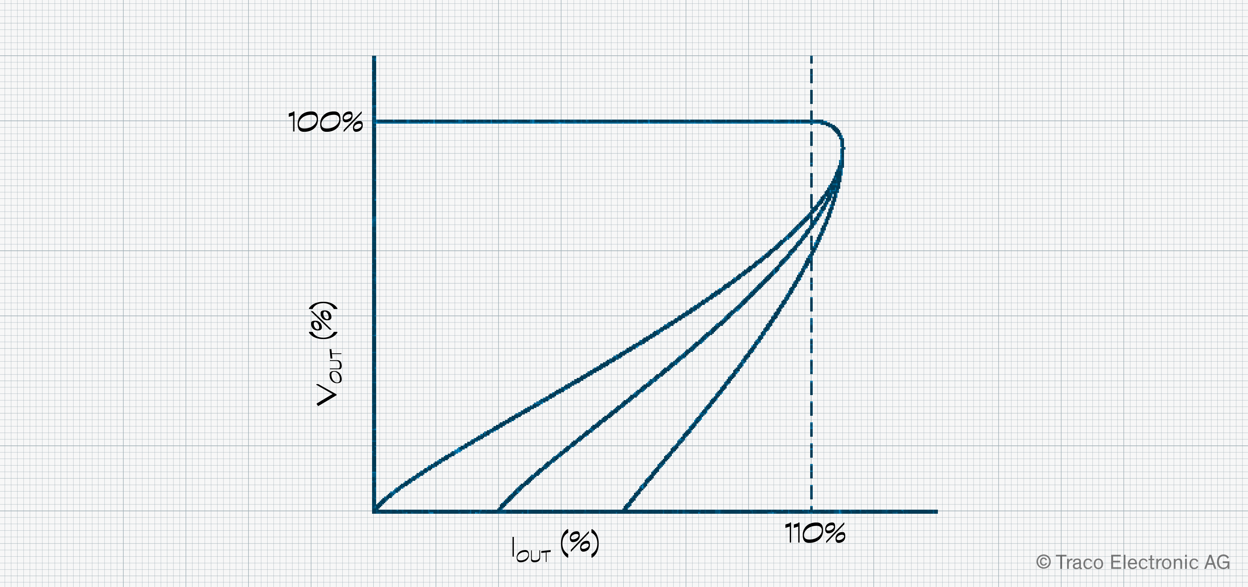
This defines the load level trigger point at which the current limitation feature starts to limit. Depending on the implementation, either the voltage (constant current limit) or current and voltage (fold back current limit) levels change. It is specified as a percentage of IOUT(max), such as 150%. More information on over-current protection can be found in the blog post.
Output voltage adjustment and set accuracy
Some power supplies allow the output voltage to be adjusted to meet the application’s needs. Whether an internal potentiometer or an external resistor should be used will be defined. The voltage set accuracy defines the deviation from the nominal output voltage given, specified in percent of VOUT(nom). If the unit is adjustable, the accuracy is for the value set during production.
Output ripple and noise
An ideal power converter will provide a perfectly clean output voltage, but, in reality, there will be some noise present. Ripple results from the charging and discharging of the output capacitors and other effects, leading to high frequency signals in the megahertz range being superimposed on the output. Noise is voltage spikes caused by the converter’s internal oscillator and switching behavior. Both contribute to a peak-to-peak signal in the millivolt range, although noise is the more significant contributor. Ripple and noise are therefore combined and given in mVp-p, usually for each different voltage out model.
Overvoltage protection
In a fault situation, the output voltage may be forced above its nominal output value. Clearly, this could damage any connected circuitry. Overvoltage protection can detect this, and its specification defines the voltage at which the mechanism cuts off the output. The point at which it engages is defined as a percentage of VOUT(nom), such as 120%. The design team can decide whether this level provides the necessary protection or is too sensitive for their application.
Start-up and hold-up timing
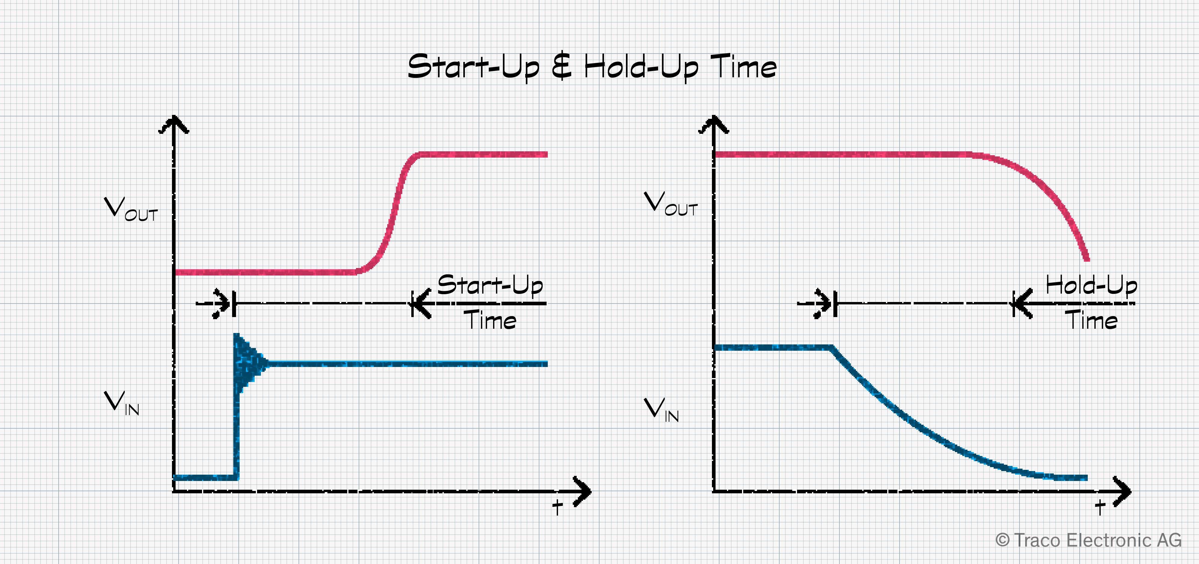
Once powered up, a power converter requires a certain amount of time before the output reaches its nominal voltage level. This duration is defined as the start-up time and is usually given in milliseconds. After being powered down, the output voltage remains at its nominal value for a short time before dropping to zero. This hold-up duration is also given in milliseconds.
Transient response
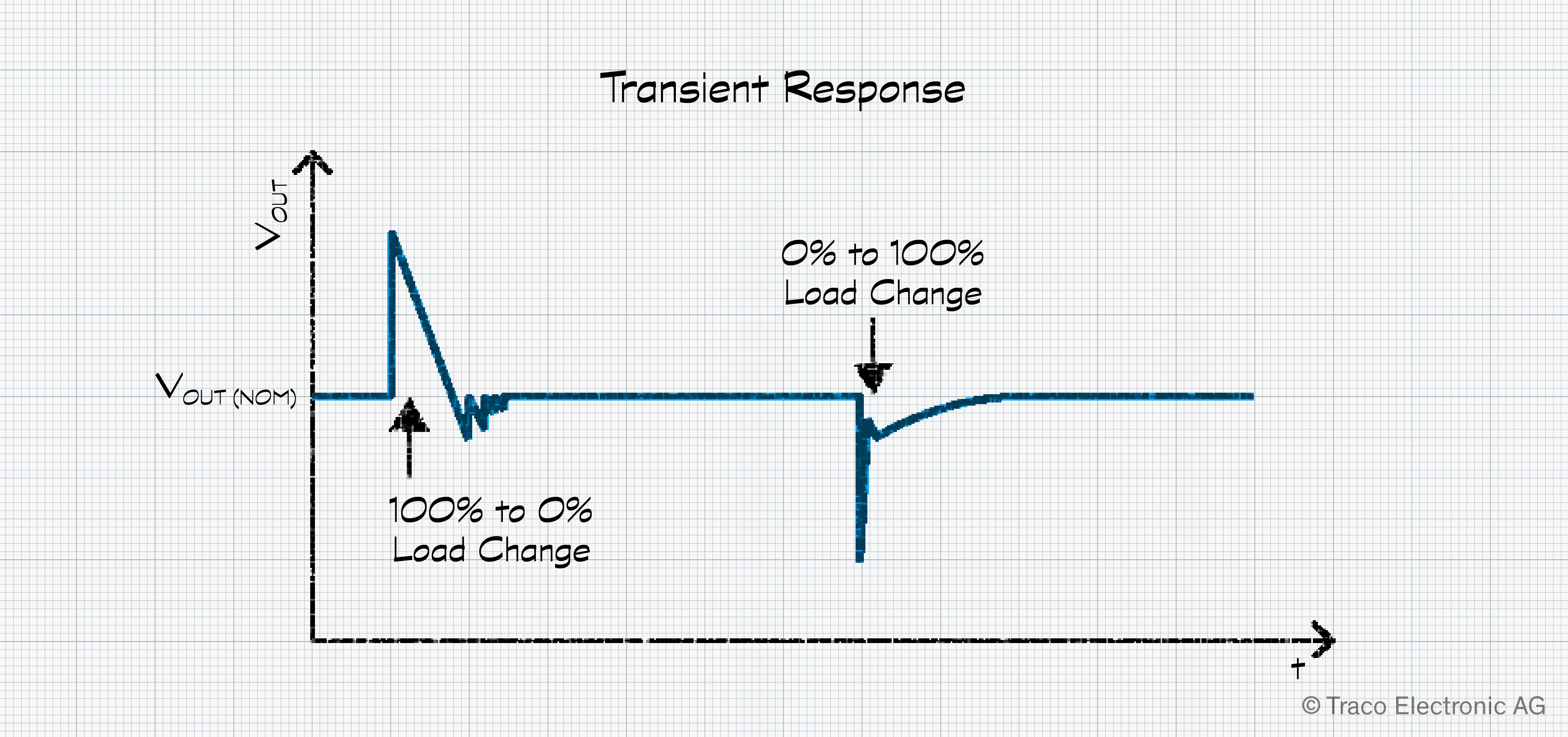
As already stated, the regulation specification focuses on how well the power converter regulates deviation in load and line. However, many loads are switched on and off, causing dynamic load changes during operation. The transient response specifies how the power converter behaves under such conditions. A load change from 100% to 0% will cause the output voltage to rise before settling after a short period. Change from 0% to 100% causes a sharp drop in output voltage before stabilizing again. In real applications, such significant changes in load are rare. To provide a value more useful to design teams, 75% to 100% load changes are used. The typical response time (microseconds) and/or response deviation (percentage) for a defined load step are given depending on the power supply model.
Temperature coefficient
Temperature also has an impact on the power converter’s output. The expected change is defined as a percentage change per Kelvin or Celsius, such as ±0.02 %/K max. The temperature referred to is the ambient temperature around the power converter; the change in output is usually compared to a reference temperature of 25°C.
Further details on power supply output specifications
In the past, some power supplies required a minimum load to ensure stable operation. However, this specification is no longer relevant with today’s advanced switching converters and is unlikely to be found except in older documentation.
So, in our second blog post on power supply specifications, we’ve covered the output specifications usually found in the datasheet. It’s up to you, as the design team, to decide which are relevant and their importance in the context of your application. In our final blog, we’ll look at some of the other general specifications that are included, providing you with the background you’ll need to feel comfortable exploring power converter datasheets.
To read our previous and next blog covering the input specifications of power converters, please click Part 1 and Part 3